Refer to Communicate with logger for step-by-step instructions on how to communicate
with a logger. If the
communication with a connected logger is successful, the following
interface regarding the current status of the logger will be
displayed: Status displays the information about the connected logger. It's read-only.
To change the information please refer to Configuration of
logger.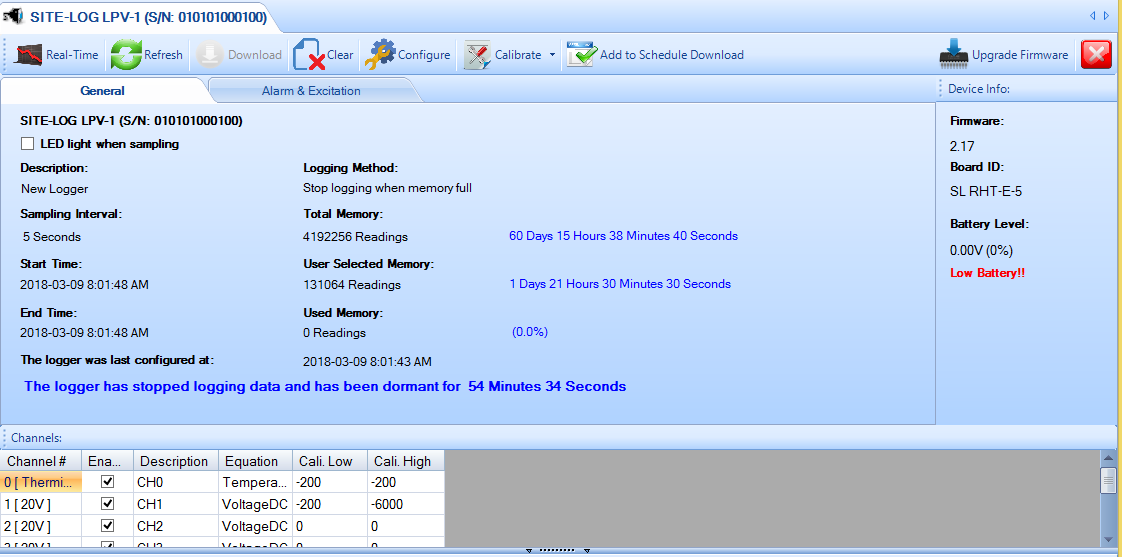
Tool bar buttons
Click to show real-time window like
this:
Click to communicate with the logger and
update the status with latest data.
Click
to display Download
dialog for backing up data from the logger.
Click to display Configuration of logger dialog for changing settings of the logger.
Click
to clear the data of the logger and start a new logging session.
Click to display Calibration dialog for custom calibration.
Click to add this logger to the Scheduled Download
Manager.
Click to upgrade firmware (this button is only visible
if newer firmware version is available)
Click
to close the current statusStatus:
LED Light When
Sampling
Specify if the on-board LED is enabled or
disabled.
Description:
Specify the description of the
logger.
Sample Interval:
Specify the time interval between
two sampling readings.
Start Time:
Specify the logging start
time.
End Time:
Specify the time the logger end
recording.
The logger was last configured at:
Specify the time
the logger was configured.
Logging
Method:
Specify if logger will stop logging or overwrite the
oldest data (FIFO) when the memory is full.
Total Memory:
Specify
the total memory the logger is capable.
User Selected
Memory:
Specify the memory that user
selected.
Used Memory:
Specify the memory the logger has
used up.
Firmware:
Specify the firmware version of the
logger.
Battery Level:
Specify the battery level of the
logger.
The logger is currently logging
data:
Specify the current status of the logger.
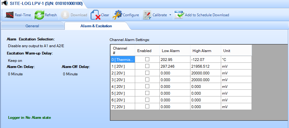
Alarm Excitation
Selection:
Specify how the control or alarm will output to C/A1
and C/A2 strips.
Excitation Warmup Delay:
Specify the warm-up delay
from the time the excitation control is turned on to the time the logger
starts to sample the current reading.
Alarm-On Delay:
Specifies a time delay before applying alarms.
Alarm-Off Delay:
Specify the delay from the time
the alarm is off the threshold to the time the
alarm is cleared.
Channel Alarm
Setting:
Channel#:
Specify the channel
number.
Alarm Enabled:
Specify if current channel will
enable or disable alarm function.
Low Alarm:
Specify
the low alarm threshold in physical unit.
High
Alarm:
Specify the high alarm threshold in physical
unit.
Unit:
Specify the unit for the alarm
thresholds.
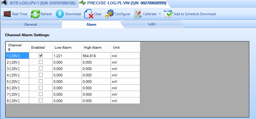
Channel Alarm
Setting:
Channel#:
Specify the channel number.
Alarm
Enabled:
Specify if current channel will enable or disable alarm
function.
Low Alarm:
Specify the low alarm threshold in
physical unit.
High Alarm:
Specify the high alarm threshold in
physical unit.
Unit:
Specify the unit for the alarm
thresholds.
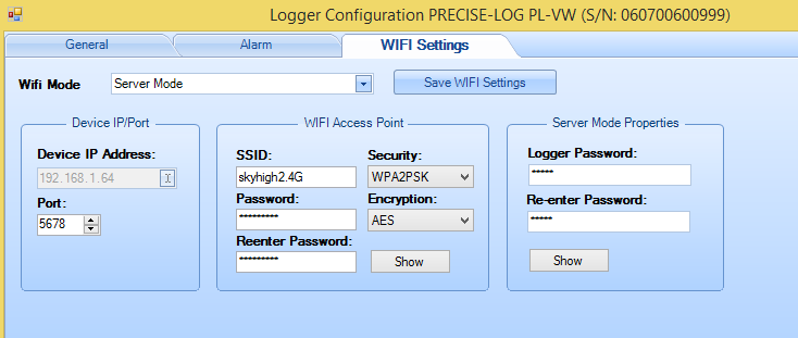
Wifi Mode:
Specify the Wifi Mode of the on-board WIFI module.
Server Mode: the logger is waiting for remote SiteView (as a client) to communicate withDevice IP Address:
The IP address of the logger that SiteView can communicate to. This IP address was dynamically assigned by the WIFI router.Port:
The port the WIFI module will use.Wifi Access Point:
This section specifies the WIFI network the logger connects to and its connection status.
Refer to Configuration of logger dialog for the available selections and options of the above each setting.